Heavy Duty Riveted Bridge Deck AASHTO H20 Loading and Fatigue Testing: Long Service Life Explored
Originally Presented at the Heavy Movable Structures, Inc. 13th Biennial Symposium October 25-28, 2010

Kenneth P. Apperson, PE – Ohio Gratings Inc.
Dr. Craig C. Menzemer, PhD, University of Akron
Introduction
Heavy Duty Riveted Bridge Deck Grating has been field proven to provide long service life for heavily loaded bridges. Examples presented include riveted steel decks that are in almost new condition after over 15 years in service and others that are still in good condition after nearly 60 years of service with no evidence of significant damage or deterioration. This is in stark contrast to the service life exhibited by some welded type bridge decks. This paper begins to examine the fatigue resistance of heavy duty riveted style bridge decks. The results from static load and fatigue cycle testing of riveted grating under AASHTO H20 loading with a 30% impact factor are presented. The testing conducted during 2009 and 2010 at the University of Akron Civil Engineering Lab has examined the static behavior of the riveted grating and has included fatigue testing of full-scale decks to well over 1 million cycles. The extra heavy load levels and worst case load location were used to accelerate the testing, and show where cracks might originate. The results also provide insight into the best methods for attachment of the riveted grating to the support structure.
Background and History of Steel Bridge Decks
Riveted heavy duty steel bridge deck was one of the first grating types developed in the early 1900’s. Because of this long history, there are many examples of riveted decks that have been in service for decades with no fatigue failures. Presented below are some examples of both riveted decks and welded type decks that contrast the life span issues. What is not known with certainty is the ADTT or Average Daily Truck Traffic for each structure.
Examples of Riveted Steel Decks:
Bay City, Michigan:
The Veterans Memorial Bridge in Bay City Michigan carries the four lane MI highway 25 over the Saginaw River. This Bascule Bridge was originally constructed in 1957. In 1994 a major renovation of the bridge included a new 5” Deep Heavy Duty Riveted Bridge Deck. The photos below were taken in February 2009. After over 15 years of service the deck is still in almost new condition.

Veteran’s Memorial Bridge Bay City, Michigan Riveted Grating installed in 1994. Like new after over 15 years in service.
Chicago, Illinois
The historic LaSalle Street Bridge in the heart of Chicago was built in 1928, and a new riveted steel bridge deck was put in service during a 1971 renovation project. This busy bridge is exposed to annual average daily traffic of about 27,000 vehicles per day. An examination in June 2008, demonstrated that the riveted grating is still providing good service after over 37 years of heavy use.
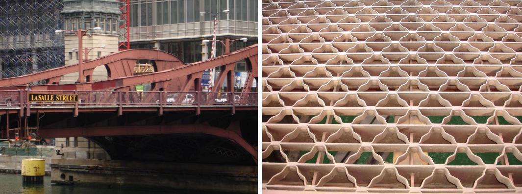
The LaSalle St Bridge in Chicago, Illinois with Riveted Bridge Deck installed in 1971 is still in good condition after over 37 years in service.
Long Island, New York:
The Robert Moses Causeway Southbound Bridge at Captree State Park was built in 1951, and in 2007, when the photos below were taken; the original riveted bridge deck was still in service.
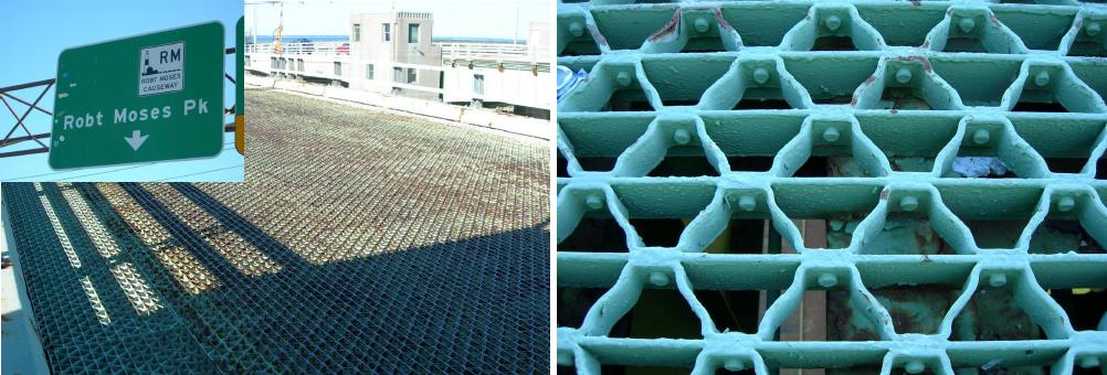
The Robert Moses Parkway Bridge in Long Island, New York with riveted steel deck installed in 1951 was still in service after 56 years.
Examples of Short Life with Welded Steel Decks:
Chicago, Illinois:
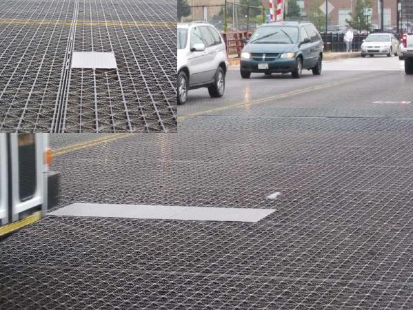
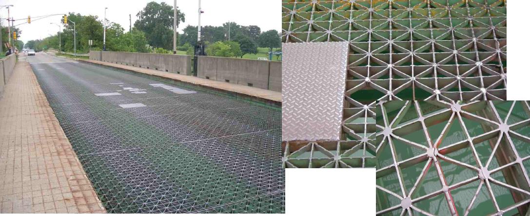
The welded type steel deck on the North Halsted Street Bridge in Chicago was installed in 1994. After less than 17 years, many of the transverse and diagonal bars have developed fatigue cracks and some bars have actually fallen out of the deck. Note the repair patch plates in several locations in the welded deck.
Grosse Ile, Michigan:
About 25 miles south of the city of Detroit, Michigan, the island of Grosse Ile is served by a 1,400 ft bridge span over the Trenton branch of the Detroit River. Most of the span is fixed, with a 340 ft swing portion near the east end. The bridge was built in 1930 with a concrete deck surface. In 1980 a welded steel deck was installed in order to lighten the dead load on the bridge to accommodate heavier trucks. By 2006 when the photos below were taken, many cracks had developed in the bars of the bridge deck. Some sections had so many missing bars that patch plates were required. In addition, the bridge deck was very noisy as the vehicles crossed. In 2007 the deck was replaced with a heavy duty riveted bridge deck.
Laboratory Testing of Riveted Deck
During 2009, a research and testing program sponsored by Ohio Gratings Inc. was started at the
University of Akron. The purpose of the project was to establish the fatigue resistance of various heavy duty riveted bridge deck types. One objective was to examine how the AASHTO H20 wheel loads with the 10” x 20” tire patch would be distributed to the various component bars within the riveted grating panel. Another objective of the research was to establish the fatigue behavior of the riveted deck, especially in the negative bending moment areas over stringer supports. It was assumed that one reason the riveted decks have performed so well in the field was due to the fact that there are no welds at the top surface where the negative bending puts the top surface in tension. The fact that the rivets are centered 0.75 inches below the top surface in a lower stress area is believed to be a major reason for the outstanding performance in the field. The test data presented is based on results for Ohio Gratings type 37R5 Lite 5” x ¼” with bearing bars of type ASTM A-36 steel.
Static Loading
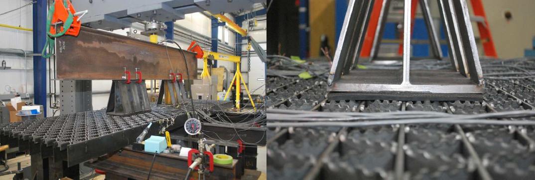
Figure 1 and the photo below show the general arrangement for the static test set-up for testing of the two span continuous riveted steel bridge deck. Support spacing was 49 inches center to center of stringers. A spreader beam was utilized and loads were placed 72 inches apart to simulate a design truck axle located to provide the maximum negative bending response. Twenty inch long sections of steel “I” beam with reinforcement plates and a 10 in wide flange were used to provide the AASHTO tire patch for an H20 loading. High durometer rubber pads were placed between the short sections of each “I” beam and the deck to act like a “tire”


Figure 1: General arrangement of static test set-up for 37R5 Lite 5” x ¼” deck.
Figure 2 shows the longitudinal strain distribution for the bearing bars acting along the negative moment region of the continuous span. Each of the strains plotted in Figure 2 is from a gage mounted 0.25 in from the top of the bar, oriented in the longitudinal direction. The distribution of strain shown represents an axle load of about 41,600 lbs, representing a fully loaded H20 truck with 30% impact applied to the wheel loads. The diagram shown in Figure 2 shows the location of the load with respect to each tire patch, centered over bearing bars 5 and 6 near the center of the panel width. From the response shown in Figure 2, it is apparent that most of the resistance is supplied by the bearing bars located directly under the load. The bearing bars adjacent to those under the load participate in the resistance, but to a much smaller extent.

Figure 2: Longitudinal strain distribution across the top of bearing bars in the negative moment region. The 10 inch dimension of the loading plate was centered over bars 5 and 6.
Figure 3 shows the longitudinal strain near the top of the bearing bars in the negative moment region when the loading is applied at the edge of adjacent panels. As before, the strains were measured using gages 0.25 inches from the top of the bar oriented in the longitudinal direction. The load was again applied to produce the maximum negative moment. The strain distribution was taken under a load of about 41,600 lbs. With the load applied at the edge of the panel, the maximum response is from the three bearing bars directly under the simulated tire patch.

Figure 3: Longitudinal strain under the maximum negative moment with the load applied at the edge of a panel.
Fatigue Tests:
Fatigue behavior of structural connections depends primarily on the detail type and the applied stress range. Fatigue test results presented here are for the same 37R5 Lite 5” x ¼” riveted steel deck represented in the static tests. As with the static tests, loading was arranged to produce the maximum negative moment over the support, and was representative of 16 kip wheel loads plus 30% impact. A small positive loading ratio, R, was maintained: wheel loads varied from 1000 lbs to 21,800 lbs, producing an effective load range of 20,800 lbs. With the maximum negative moment occurring over the support, the details of interest were the rivet connections between the main bearing bar and adjacent reticuline bars as well as the attachment of the deck to the supporting structure. In this case, the supporting structure was represented by a series of “W” beams intended to act like stringers.
Figure 4 shows one crack that developed during fatigue testing after 1,300,000 cycles in one of the bearing bars of the deck. The section of deck where this piece was removed was directly over the center support, or that area subjected to maximum negative bending. What is interesting to note is that the crack originated from the fillet weld used to attach the deck to the test fixture. In a number of instances, field installation would require fillet welding of the bearing bars to supporting steel. For the tests conducted in the laboratory, a plate was welded to the bottom of the bearing bars and was then mechanically fastened to the simulated steel stringers.

Figure 4: Section of bearing bar after fatigue test of 37R5 Lite 5” x 1/4” steel deck.
Located directly over a support, the fatigue crack that developed in Figure 4 would have experienced compression due to bending and shear. Tensile residual stress fields exist adjacent to a vast majority of weldments, due to the uneven heating and cooling that occurs during the joining process. Often these local residual stresses may be on the order of the yield point of the base metal. It is likely that the area close to the fillet weld experienced a net cyclic stress that was tensile. Inclination of the crack is most likely the result of the presence of shear as well.
Figure 5 is a Scanning Electron Micrograph (SEM) image of the fracture surface in the area near the fillet weld. While there is a significant amount of mechanical damage from the surfaces coming into contact during negative bending, there are a series of what appear to be ridges or striations present, indicative of fatigue crack growth.

Figure 5: Area near the weld showing mechanical damage with some indication of striations.
Figure 6 is an SEM micrograph taken in the overload region. The fracture surface has a rough macroscopic appearance. Upon closer examination, the matrix shows evidence of localized cracking and the formation of microvoids, indicative of tensile overload. Therefore, it is believed that the tensile fracture of this section up to the top of the grating resulted from the crack which started near the weld area. During the testing of this deck, no fatigue cracks were observed in the area of the rivet.

Figure 6: Overload region of fracture surface.
Conclusion:
The laboratory testing confirms that the heavy duty riveted bridge deck is very resistant to fatigue cracking. This type deck can be relied upon to provide decades of service even when exposed to heavy truck loading. When a crack finally was initiated in the test panel after 1,300,000 cycles of extreme worst case loading, it started in the area of the welded attachment at the bottom of the grating well away from the riveted connections. This suggests the design of the attachment to the stringers is important.
Alternate Attachment Systems:
Several options are available for modification of attachment system. One option is to raise the welded fastener plate closer to the neutral axis of the bearing bars as shown in figure 7. This will move the residual stress area around the welds into an area where they will be subjected to much lower levels of stress reversal during live loading. The fastener plates would then be attached to the stringers by bolted connections as shown. Another option is to use an attachment design that eliminates the need for welding the fastener plate to the bearing bars. One way to accomplish this is to use a bearing bar angle rather than flat bar. This configuration is shown in figure 8. This method allows direct bolting of the bearing bars to the support stringers thus eliminating the welded fastener plate. The continuing research and testing program will include fatigue cycle testing with heavy duty riveted bridge deck using these alternate attachment systems.

Figure 7 – Fastener Plate welded up 1 inch from the bottom of the bearing bar.

Figure 8 – Bearing Bar Angles provide a horizontal leg for bolted attachment to the stringers with no welding required.
HMS 13th Biennial Symposium Heavy Moveable Structures
Heavy Duty Riveted Bridge Deck
Long Service Life Explored


 Castings & Forgings
 Bulk Material Handling
 Electrical & Electronic Components
 Flow Instrumentation
 Hardware
 Material Handling Equipment
 Metal Cutting Services
 Metal Forming Services
 Metal Suppliers
 Motion Control Products
 Plant & Facility Equipment
 Plant & Facility Supplies
 Plastic Molding Processes
 Pumps & Valves
 Recycling Equipment
 Rubber Products & Services